Privacy statement: Your privacy is very important to Us. Our company promises not to disclose your personal information to any external company with out your explicit permission.
The present utility model is further described below through embodiments in conjunction with the accompanying drawings.
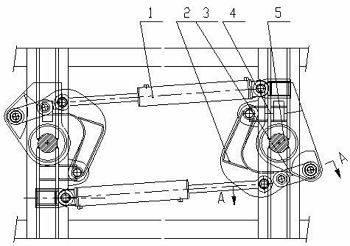
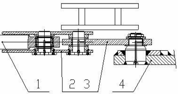
As shown in Figure 1 and Figure 2, the independent cylinder steering mechanism mainly includes a steering cylinder 1, a crank 2, a connecting rod 3, and a suspension plate, 4 and the intermediate shaft 5, the support of the steering cylinder 1 is installed on the frame, the crank 2 and the connecting rod 3 play the role of transmitting the thrust of the cylinder.

The suspension plate 4 is mechanically connected with the wheel set, the suspension plate can rotate around the intermediate shaft 5, and a tapered roller bearing is installed on the intermediate shaft 5 to bear the axial and radial loads transmitted from the vehicle. Working process: When the vehicle needs to be turned, the control system sends a command to the steering proportional valve of the hydraulic system, and the control pressure oil enters the steering cylinder 1, and the steering cylinder 1 pushes the crank 2 through the connection.
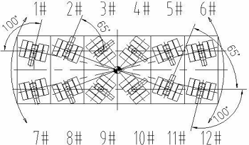
The transmission of the rod 3 transmits the steering force to the suspension plate 4, and the suspension plate 4 is mechanically connected with the wheel set. Under the action of the steering force, the suspension plate 4 rotates around the intermediate shaft 5 to realize the steering of the wheel set. The intermediate shaft 5 and a pair of tapered roller bearings mounted on it mainly play the role of bearing the axial and radial loads transmitted from the vehicle. In this steering mechanism, the steering angle is -65°~+100°, each steering mechanism works independently, cooperates with the electronic control system to achieve arbitrary control of each suspension device, and finally realizes various steering modes.

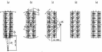
Figure 4 is the description of the steering mode, the small squares in various directions in the figure represent each suspension wheel set; Figure 4(a) is the lateral eight-character mode: the longitudinal wheel set of the vehicle maintains the lateral direction, and the wheel set is set to any one in the longitudinal direction. The turning center rotates, and the vehicle travels around the longitudinal center; Figure 4(b) is the center turning steering mode: each wheel set sets the center of the vehicle as the turning center, and the vehicle realizes in-situ steering with zero inner turning radius; Figure 4(c) shows Figure 8 steering mode: the rear wheel set of the vehicle maintains the forward direction, the front wheel set is set to rotate around any lateral center of rotation, and the vehicle runs around the lateral center; Figure 4(d) is the oblique mode: each wheel set is steered The vehicle can be controlled to face the same direction, and the vehicle can run obliquely; Figure 4(e) is the lateral mode: each wheel set of the vehicle is set to the lateral direction, and the vehicle can run laterally; other steering modes: since each wheel set can be controlled independently, the vehicle can also Complete some other steering modes, such as the half-eight steering, head swing, and tail swing standby mode used in normal driving.

The modular car is made up of 12 suspension wheel sets evenly distributed. When the center rotates, each suspension wheel set is required to be located in the tangential direction of the rotation center. When the steering angle is greater than ±90°, the state of the wheel set is generally based on the longitudinal center axis. Mirror distribution, if this method is used in the new steering mechanism, the angle of the 1# and 12# wheel sets will be less than -65°, however, its mechanical structure cannot meet the angle requirements in this direction, so these two The wheel set rotates in the reverse direction to +100°, and the electronic control system needs to judge the properties of the two wheel sets. If the wheel set is a driving wheel, it needs to control its movement direction to be opposite to the usual situation; if it is a driven wheel, no control is required. It will adjust itself according to the direction of vehicle movement.
In a word, the independent oil-cylinder steering mechanism includes a steering oil cylinder, a crank, a connecting rod, a suspension plate and an intermediate shaft. The steering cylinder pushes the crank through the transmission of the connecting rod, and transmits the steering force to the suspension plate. The suspension plate and the wheel set are mechanically connected. Under the action of the steering force, the suspension plate rotates around the intermediate shaft to realize the steering of the wheel set. The intermediate shaft and the installation A pair of tapered roller bearings on it mainly play the role of bearing the axial and radial loads transmitted by the vehicle; through the independent oil cylinder structure and the electronic control system, each suspension is controlled independently, and the asymmetric distribution of the steering angle is ensured. , and finally realize a variety of different steering modes.
LET'S GET IN TOUCH

Privacy statement: Your privacy is very important to Us. Our company promises not to disclose your personal information to any external company with out your explicit permission.

Fill in more information so that we can get in touch with you faster
Privacy statement: Your privacy is very important to Us. Our company promises not to disclose your personal information to any external company with out your explicit permission.