Privacy statement: Your privacy is very important to Us. Our company promises not to disclose your personal information to any external company with out your explicit permission.
This article relates to an independent oil cylinder steering mechanism for a hydraulic module vehicle, in particular to a dedicated independent oil cylinder steering mechanism for SPMT hydraulic modular transport vehicles and related equipment.
In the current hydraulic modular transport vehicle and related equipment, in order to realize the steering of the whole vehicle, two steering mechanisms are used: the first method is a rack and pinion steering mechanism, which is mainly composed of a suspension device, a gear, a rack, and an oil cylinder and connecting flange. When working, the extension of the oil cylinder drives the rack to move in a straight line, the rack pushes the gear to rotate, and the transmission through the connecting flange finally drives the suspension device to rotate. The steering angle of this steering mechanism can reach more than ±110°. The second mode is a worm gear steering mechanism, which is composed of a hydraulic motor, a reducer, a worm gear, a worm, a slewing bearing and a suspension device. The hydraulic system supplies the hydraulic motor with pressure oil, which is decelerated by the reducer to drive the worm to rotate, the worm to drive the worm wheel to rotate, the outer side of the slewing bearing is integrated with the worm wheel, and the rotation of the worm wheel drives the suspension device to rotate to realize the rotation of the mechanism. The steering angle of this steering mechanism can reach ± 130° or more.
The original two steering modes have complex structures, one is difficult to manufacture, and the other is difficult to guarantee the stability, and the manufacturing cost is high. The new steering mechanism will be a useful addition to this field.
In order to solve the above problems, the new steering structure provides an independent cylinder steering mechanism for a hydraulic module vehicle, and handles the influence of the steering angle of the new steering mechanism being less than ±90° on different steering modes.
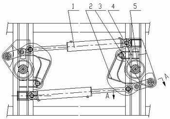
The independent oil cylinder steering mechanism consists of a steering oil cylinder 1, a crank 2, a connecting rod 3, a suspension plate 4 and an intermediate shaft 5. The support of the steering oil cylinder 1 is installed on the frame, and one end of the steering oil cylinder 1 is connected to the crank 2 through a pin shaft. 2. One end of the connecting rod 3 is connected to the connecting rod 3, and the other end of the connecting rod 3 is connected to the suspension plate 4. One end of the suspension plate 4 is fixed on the intermediate shaft 5 and can rotate around the intermediate shaft 5; the steering cylinder 1 is connected to the control system.
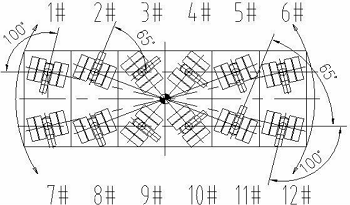
In order to adapt to the flexible operation of the hydraulic module car in a small space, it needs to meet a variety of steering modes including center rotation. In the usual way of thinking, the vehicle needs to meet the steering angle of more than ±90°, but due to the width of the module car Due to the limitation, the arranged independent oil cylinder steering mechanism is difficult to meet the angle requirement of ±90°. The utility model can meet various required steering angles under the condition that the vehicle design steering angle is -65°~+100° through reasonable arrangement. Mode, the inventor of the present invention has completed the present utility model through research and practice, and the present utility model can save the cost of the steering system of the hydraulic module vehicle by about 50%.
This steering structure reasonably arranges the steering angle, through the asymmetrical arrangement of the angle, to achieve the angle required to realize various steering modes, and utilizes the characteristics of the linkage mechanism driven by the independent oil cylinder to replace the existing more complex racks and pinions and worm gears Worm steering mechanism.
Figure 1 is a schematic diagram of the structure.

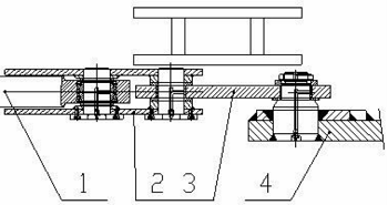
Figure 2 is a cross-sectional view taken along line A-A of figure 1.

Figure 3 Schematic diagram of the center rotation of the new steering mechanism.
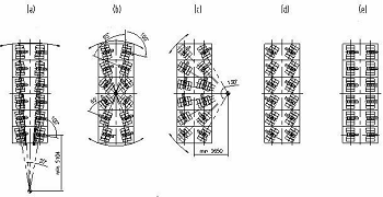
Figure 4 Steering mode of the new steering mechanism. Among them: (a) is the lateral eight-figure steering, (b) is the center turning steering, (c) is a figure-of-eight turn, (d) is a diagonal run, and (e) is a sideways run. 
Labels in the figure: 1 is the oil cylinder, 2 is the crank, 3 is the connecting rod, 4 is the suspension plate, and 5 is the intermediate shaft.

LET'S GET IN TOUCH

Privacy statement: Your privacy is very important to Us. Our company promises not to disclose your personal information to any external company with out your explicit permission.

Fill in more information so that we can get in touch with you faster
Privacy statement: Your privacy is very important to Us. Our company promises not to disclose your personal information to any external company with out your explicit permission.